
M140 |
|
|
|
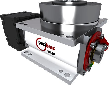
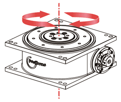
The M140 Rotary Indexing Table is recommended for small applications that don’t require heavy loading. Compact and light, it can be easily installed by fastening 4 screws to its body. It can be installed horizontally, vertically, or inverted (upside down). Ideal for applications such as:
|
 |
|
| Rotating plate diameter: | 140 mm5.512 in |
| Diameter of the cable pass-through hole: | 12 mm (hole has a 15º deviation)0.472 in (hole has a 15º deviation) |
| Direction of rotation: | Clockwise, counter-clockwise, or alternating both |
| Number of steps per rotation: | Indexed cam of: 2, 3, 4, 5, 6, 7, 8, 9, 10, 11, 12, 13, 14, 15, 16, 18, 20, 21, 22, 24, 26, 27, 28, 30, 32, 33, 36 (others on request), or Continuous cam |
| Motor voltage: | 220 V / 380 V / 440 V |
| Motor frequency: | 50 Hz / 60 Hz |
| Motor power: | 0.09 to 0.25 KW |
| Weight without geramotor: | approx. 12 Kgapprox. 26.45 lbs |
| Weight with geramotor: | approx. 16 Kg (varies depending on the applied geramotor)approx. 35.27 lbs (varies depending on the applied geramotor) |
| Stop precision: | ±0.020 mm at 50 mm center radius±0.000787 in at 50 mm center radius |
| Stop repeatability: | ±0.010 mm at 50 mm center radius±0.000395 in at 2 in center radius |
| Inductive sensor: | PNP NO (10 V to 36 V) |
| Load | Description | Values |
|---|---|---|
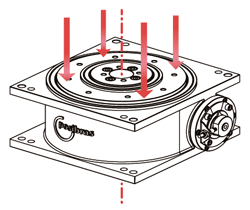 |
A- Maximum axial load (*): Represents the total mass evenly distributed over the rotating plate (or total weight)(*) – the maximum total load refers to the forces on the rotating plate. This doesn’t mean that the indexing table will be able to rotate such mass, as the rotation depends on three factors:
|
400 Kg880 lbs |
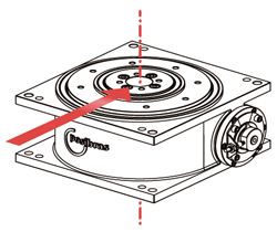 |
B- Maximum radial load: Represents forces perpendicular to the center of the rotating plate, usually exerted by actuators outside the indexing tables, aligned to the center of this plate |
200 Kg440 lbs |
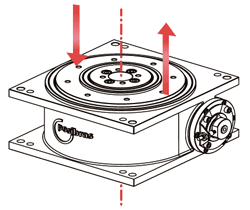 |
C- Maximum vertical torque: Represents the imbalance of masses on the rotating plate, or the twist of this rotating plate usually caused by actuators outside the indexing table that exert axial force on only one side of the rotating plate |
500 Nm368 ft.lbs |
 |
D- Maximum horizontal torque: represents external forces in the direction of rotation of the indexing table, forcing the rotating plate to turn or brake. |
110 to 400 Nm295 ft.lbs |
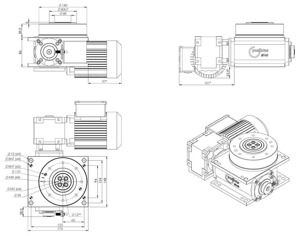
M140 main dimensions
(*) – measurements can vary depending on the geramotor attached to the indexing table (**) – only in M140, 32 mm1.26 in below the beginning of the cable pass-through hole, a 15º deviation is found |

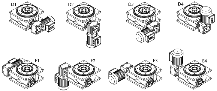
M140 geramotor assembly position
|
Download the instruction manual – click on the icon below |

Download CAD 3D part
|
| rotary index table, indexer, machine building, rotary machines, indexing ring, automation equipment, linear machine, rotary stage, rotary index, rotary indexing, rotary indexer, indexers, rotary transfer, indexing rotary tables, assembly machinery, assembly machines, assembly automation equipment, indexing conveyor, assembly conveyor |