
M340 |
|
|
|
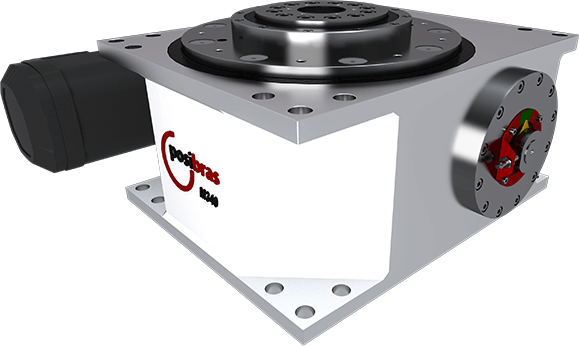
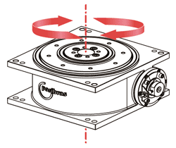
The M340 Rotary Indexing Table is suitable for high-load applications. Its body is made from welded steel plates, ensuring greater strength. Robust, it can be installed by securing 6 bolts to its body. It includes guide holes in both the body and the output flange, facilitating its installation. It can be mounted horizontally, vertically, or inverted (upside down). Ideal for applications such as:
|
 |
|
Technical Characteristics |
|
| Rotating plate diameter: | 340 mm13.38 in |
| Cable pass-through hole diameter: | 60 mm (through)2.36 in (through) |
| Rotation direction: | Clockwise, counterclockwise, or alternating both |
| Number of steps per turn: | Indexed cam of: 2, 3, 4, 5, 6, 7, 8, 9, 10, 11, 12, 13, 14, 15, 16, 18, 20, 21, 22, 24, 26, 27, 28, 30, 32, 33, 36 (others upon request), or Continuous cam |
| Motor voltage: | 220 V / 380 V / 440 V |
| Motor frequency: | 50 Hz / 60 Hz |
| Motor power: | 0.55 to 4.0 KW |
| Weight without gearmotor: | approx. 175 Kg approx. 385 lbs |
| Weight with gearmotor: | approx. 255 Kg (varies according to the applied gearmotor)approx. 562 lbs (varies according to the applied gearmotor) |
| Stop accuracy: | ±0.012 mm at a 50 mm center radius±0.00047 in at a 2 in center radius |
| Stop repeatability: | ±0.006 mm at a 50 mm center radius±0.00024 in at a 2 in center radius |
| Inductive sensor: | PNP NA (10 V to 36 V) |
| Load | Description | Values |
|---|---|---|
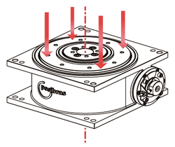 |
A- Maximum axial load (*): Represents the total mass evenly distributed on the rotating plate (or total weight)(*) – the total maximum load refers to the forces on the rotating plate. This does not mean that the indexing table will be able to rotate such a mass, as the rotation depends on three factors:
|
7000 Kg15430 lbs |
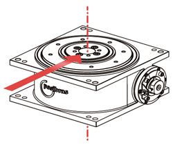 |
B- Maximum radial load: Represents forces perpendicular to the center of the rotating plate, usually exerted by actuators outside the indexing tables, aligned to the center of this plate |
1300 Kg2860 lbs |
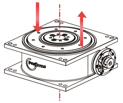 |
C- Maximum vertical torque: Represents the imbalance of masses on the rotating plate, or the twisting of this rotating plate usually caused by actuators outside the indexing table that exert axial force on only one side of the rotating plate |
10000 Nm7370 ft.lbs |
 |
D- Maximum horizontal torque: Represents external forces in the direction of rotation of the indexing table, forcing the rotating plate to rotate or brake. |
3500 to 6800 Nm2580 to 5015 ft.lbs |
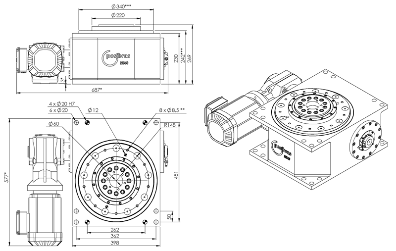
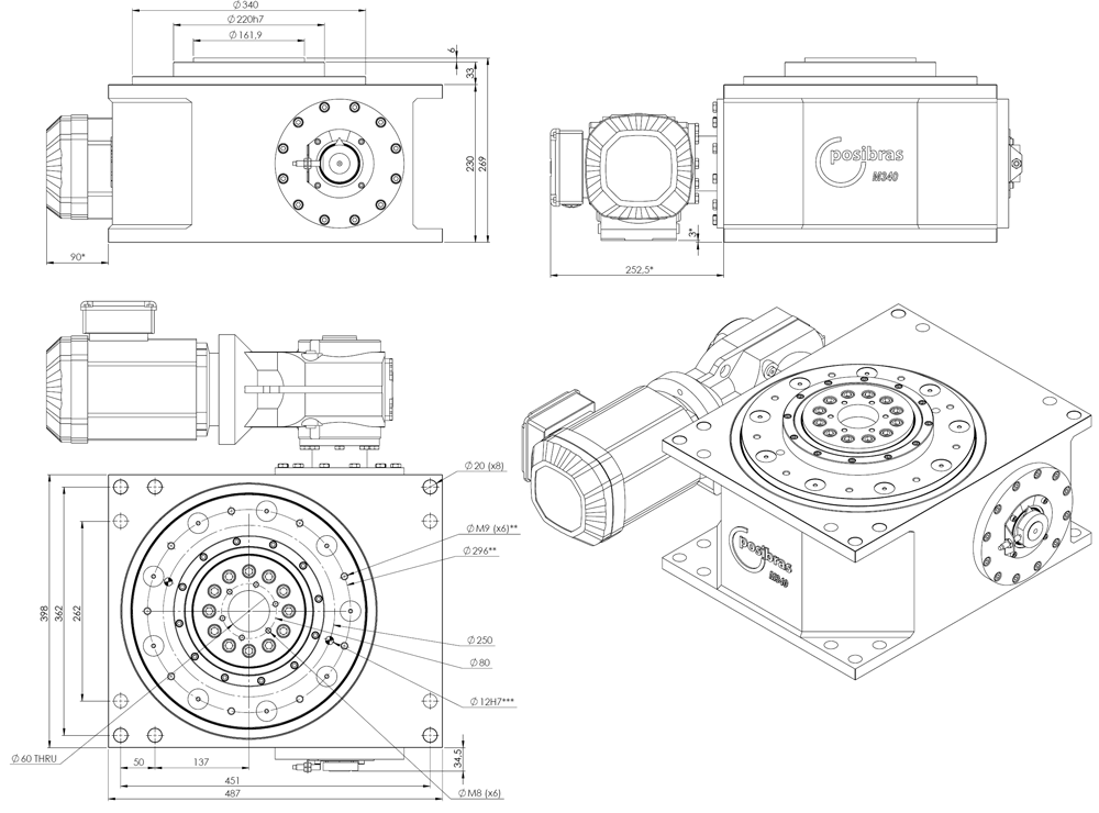
M340 main dimensions
(*) – measurements can vary depending on the geramotor attached to the indexing table |
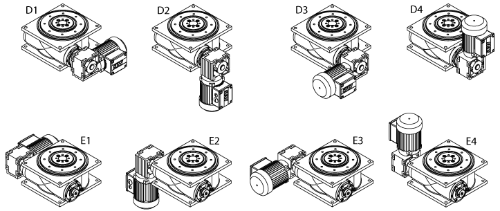
M340 geramotor assembly position
|
Download the instruction manual – click on the icon below |

Download CAD 3D part
|
| rotary index table, indexer, machine building, rotary machines, indexing ring, automation equipment, linear machine, rotary stage, rotary index, rotary indexing, rotary indexer, indexers, rotary transfer, indexing rotary tables, assembly machinery, assembly machines, assembly automation equipment, indexing conveyor, assembly conveyor |