
Moment of Inertia Calculation in Solidworks or Inventor
| In mechanics, the moment of inertia, or mass moment of inertia, expresses the difficulty in changing the motion state of a rotating body. The unit is typically Kg.m2 (kilogram times square meter). The further the mass is from the center of rotation, the greater the moment of inertia.
Calculating the moment of inertia for your assembly is crucial for determining the best indexing table for your needs, without risking oversizing and incurring excessive costs, or undersizing and not meeting the required resistance. There are several ways to determine the moment of inertia: We’ve created the step-by-step guide below to help identify the moment of inertia of your assembly that will be moved by the indexing table, using the CAD tools Solidworks and Inventor. Other CADs have similar methods for this calculation. Please consult your CAD manufacturer for the exact procedure. |
 |
Solidworks
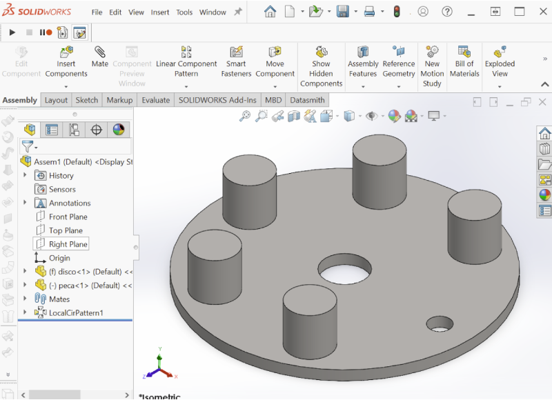
| 1 – Create an assembly with all the items that will be moved by the indexing table (disc, devices, screws, parts, etc). All items should have correct dimensions and masses/materials defined. |
 |
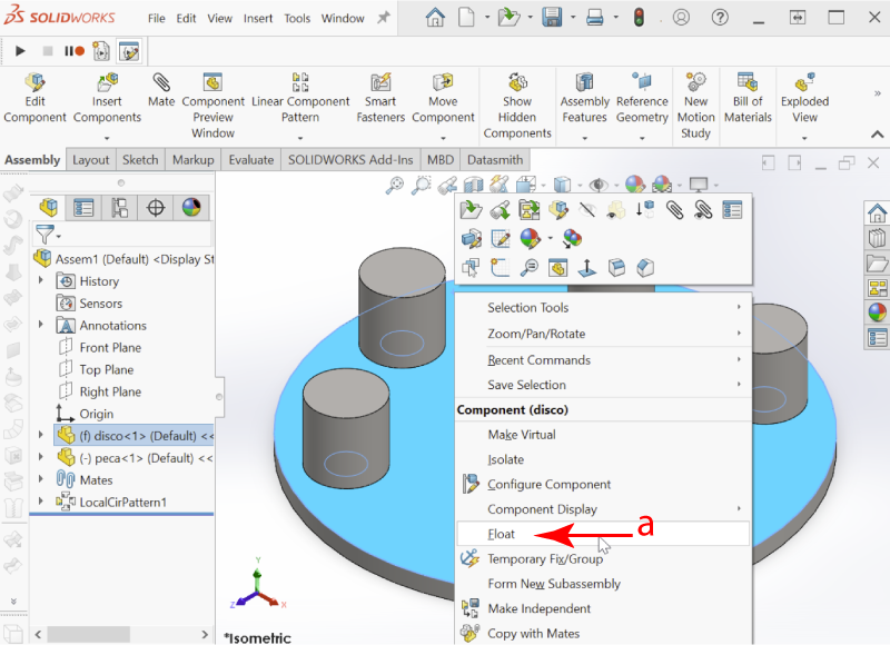
| 2 – Let the assembly float by right-clicking on the assembly (a). |
 |
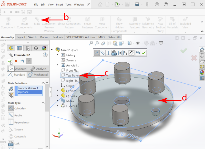
| 3 – Align the rotating disc of the assembly to one of the standard planes using the Assembly icon (clips). The positioning should be “coincident”. |
 |
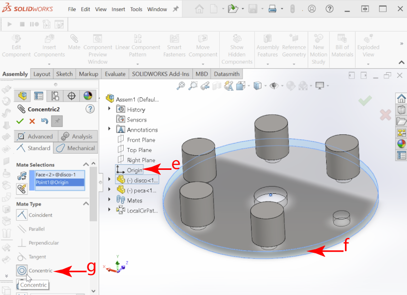
| 4 – Also align the Solidworks Origin with the center of the assembly’s rotating disc using the Assembly icon (clips). The positioning should be “concentric”. |
 |
| 5 – With no object selected, click on the “Evaluate” menu, then “Mass Properties”. When the moment of inertia calculation screen appears, click on the Options button and change the mass units to “Kilograms” and length to “Meters”. |
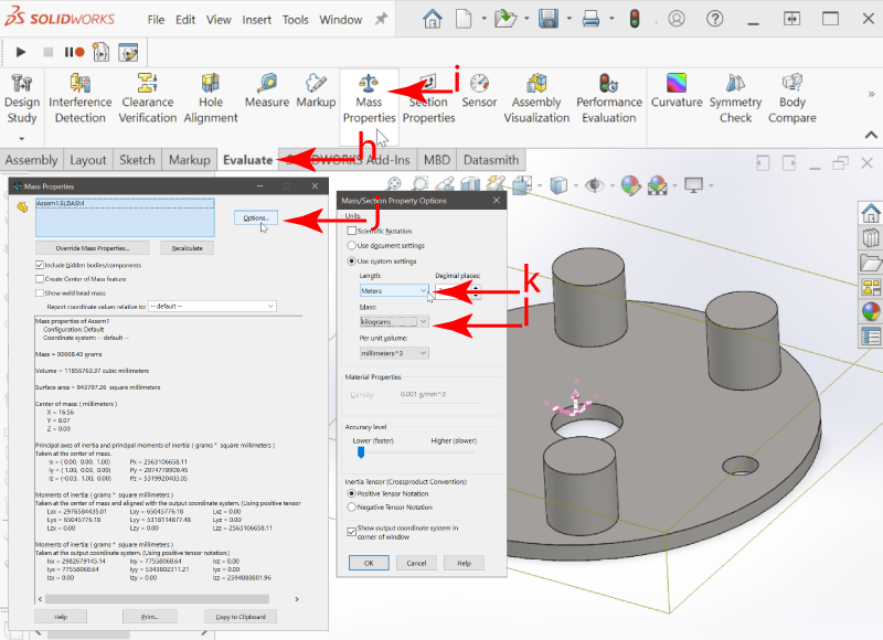 |
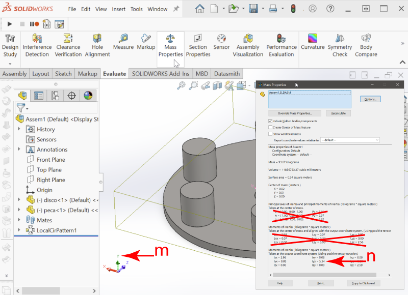
| 6 – Position the assembly so that you can read the moment of inertia data and see the colored UCS in the bottom left of the screen in the same view. Check which UCS letter represents the axis your assembly will rotate around. In the example below, the assembly will rotate around the Y-axis, so the moment of inertia is shown by Solidworks under item lyy. |
 |
Inventor
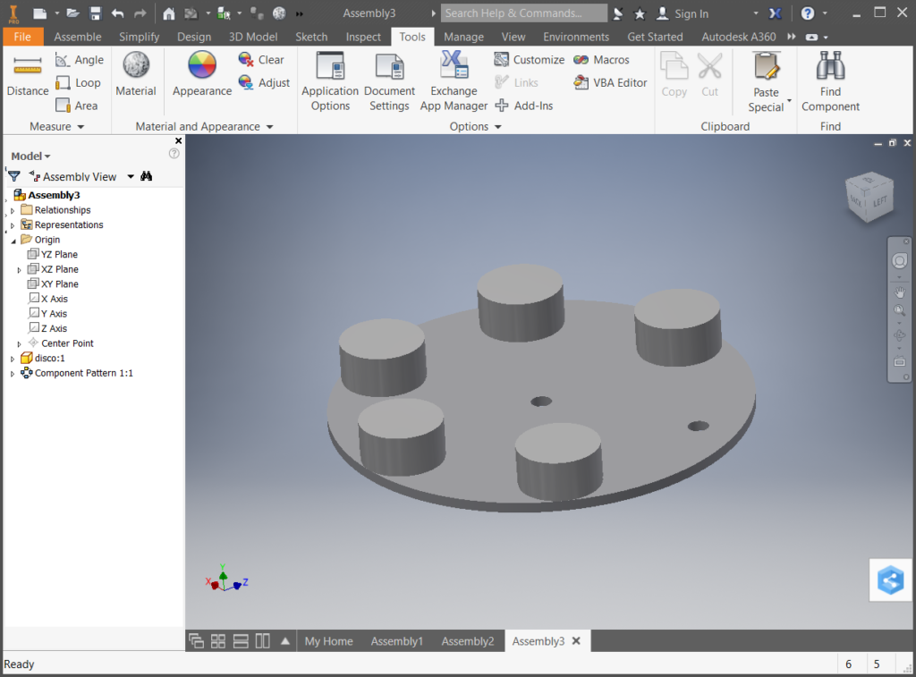
| 1 – Create an assembly with only the items that will be moved by the indexing table (disc, devices, screws, parts, etc). All items should be correctly defined in terms of dimensions and mass/material. |
 |
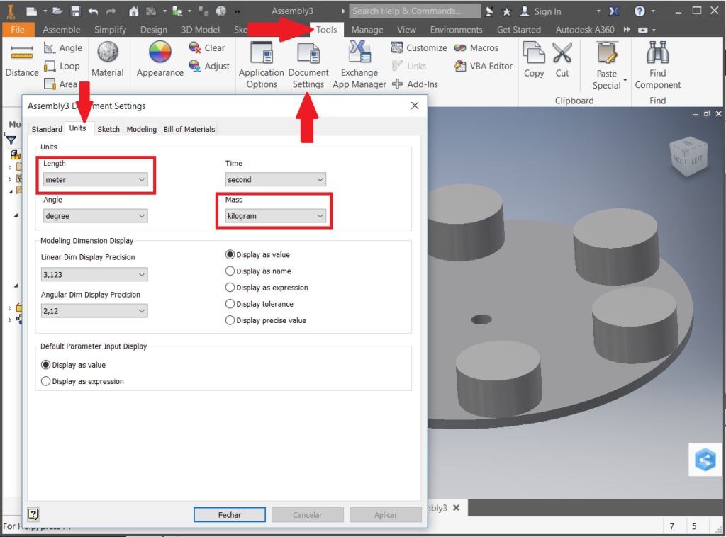
| 2 – Change the distance measurement units to meters and the mass units to kilograms using the Tools / Document Settings menu. In the document properties screen, click on “Units” and change the Length unit to meter and Mass to Kilogram. |
 |
| 3 – Align the rotating disc of the assembly with the XZ plane using the “Constrain” icon. This way, the rotation axis of the disc will be the Y-axis. |
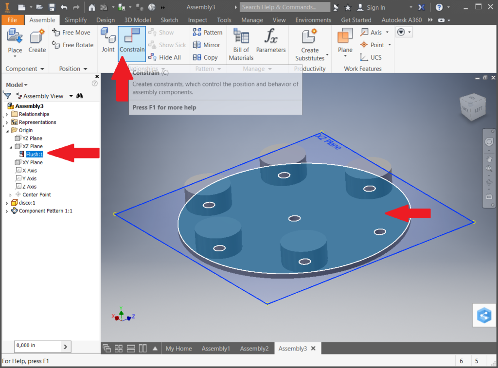 |
| 4 – Also align the Inventor’s Origin with the center of the assembly’s rotating disc using the “Constrain” icon. |
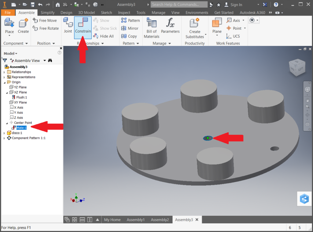 |
| 5 – Right-click on the first item in the left menu and then left-click on the “iProperties” submenu. A new assembly properties screen will appear. |
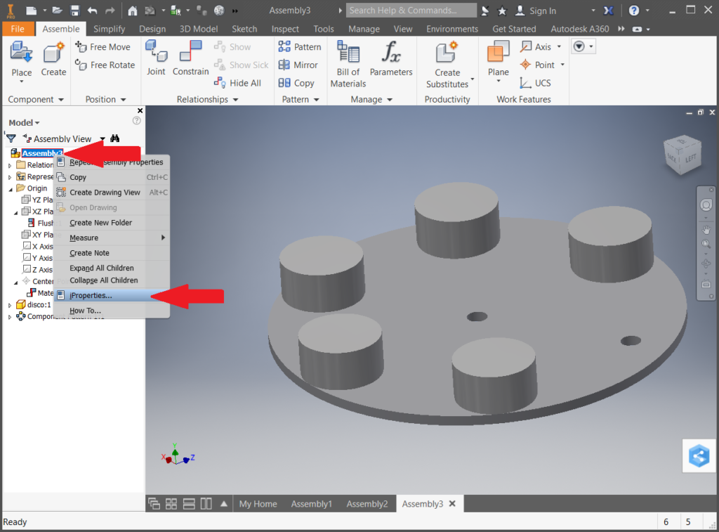 |
| 6 – In this new properties screen, click on the “Physical” tab, then the “Update” button, followed by the “Principal” button. The moment of inertia values related to the objects that will rotate around the Y-axis are shown in the I2 box. Press the “Print Screen” key on your computer and send the image of the part + moment of inertia to Posibras. The image below is an example of how it should be sent. |
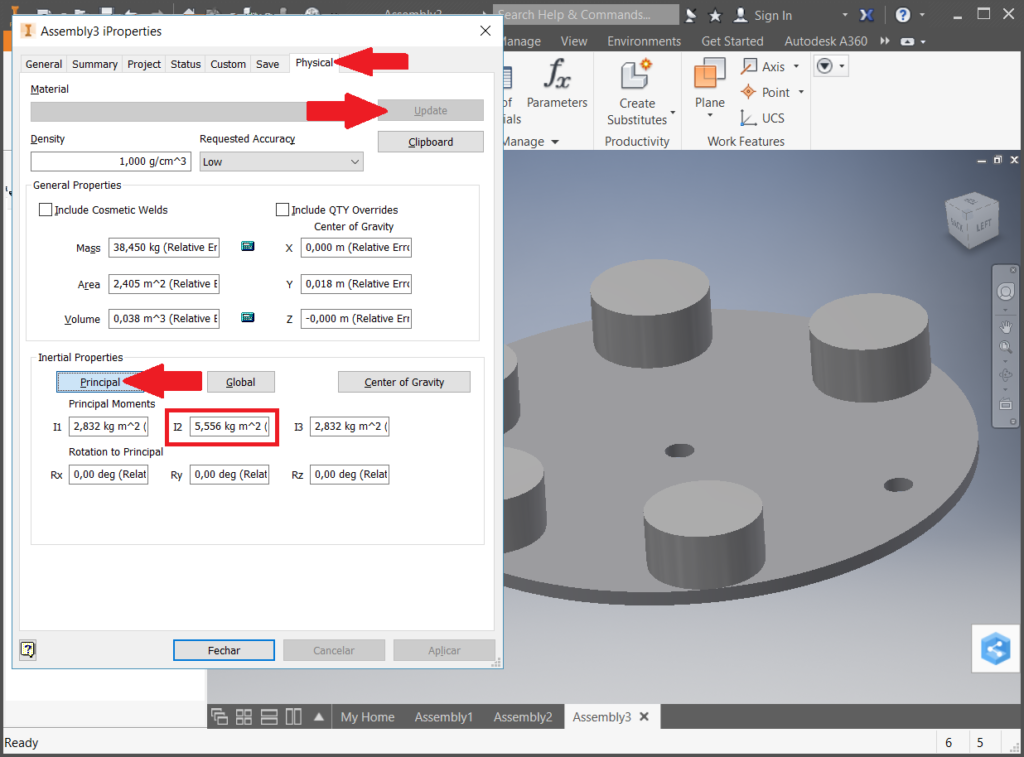 |
| In the example above, the value we are looking for is I2 5,556 Kg.m2, as the assembly will rotate around the Y-axis. If the moment of inertia unit is different from Kg.m2, you’ll need to follow steps 2, 5, and 6. |
| rotary index table, indexer, machine building, rotary machines, indexing ring, automation equipment, linear machine, rotary stage, rotary index, rotary indexing, rotary indexer, indexers, rotary transfer, indexing rotary tables, assembly machinery, assembly machines, assembly automation equipment, indexing conveyor, assembly conveyor |